What does it do:
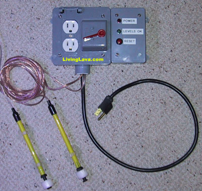
The Water Level Alarm (WLA) allows you to protect your pump (and carpets) if the water levels in your tank or sump should rise or fall outside acceptable levels. You specify how low or high the levels are allowed to be via float switches. Simply wire as many as you wish in series. Most float switches are reversible, meaning you can switch them from normally on to normally off. This means that you change a float switch to break the current when the level rises too high or when the level drops too low. I used 2 in my design, one to turn off the pump if the sump level falls too low or if the tank level rises too high. If you are thinking about building a switch to simply replace evaporated water please refer to my DIY Float Switch.
Schematic:
NOTE: During normal operation all switches and relays are closed. The button is normally open.
What you will need:
1 12VDC Transformer
2 12VDC SPDT (or DPDT) relays (RS 275-206); one should be rated to handle the amperage of your pump(s)
Floatswitch(es) (Grainger 2A554); as discussed above use as many as you like
1 SPST Momentary Pushbutton Switch (RS 275-646)
1 Standard Light switch
1 Standard AC outlet
1 Powercord with 3 pronged plug
1 Housing; outdoor outlet boxes work well and are water resistant
1 Buzzer or chime (RS 273-071); optional
Soldering iron, solder, heavy duty electrical wire, light duty electrical wire, wire strippers, multimeter, screwdrivers, long nose pliers, etc.
Schematic Overview:
Although it is up to you to isolate current flowing through the float switches as best you can it is recommended to keep the voltage as low as possible in case of stray voltage. As with any float switch it is recommended a grounding probe be used. You may substitute a lower voltage transformer if you wish, but realize the coil voltage of the relays must match the transformer voltage.
Lets start with the top circuit. For this circuit use heavy gauge electrical wire. The black, or live, wire is hooked to the master switch, I used a standard light switch. You should also wire the transformer from the bottom circuit to the same switch. From the switch solder a connection to the normally open pin of the relay. Solder a wire from the switch pin to the outlet. Connect the other side of the outlet to the white wire. If you purchased a 3 pronged powercord connect the green ground wire as well.
|
|
This is a diagram from the RadioShack 275-206c 12VDC relay. It is a DPDT relay, but a SPDT will work. Note the coil is pins 13 & 14. Think of the coil voltage as the signal required to make the relay switch from normally closed to normally open. Pin 9 is the switch. Pins 1 and 5 are the contacts, normally closed and normally open respectively. When the signal voltage is not applied to the coil pins 1 & 9 are closed. When the signal voltage is applied to the coil pins 5 & 9 are closed. Note: the voltage of the coil only pertains to the signal required to make the contacts switch. The contacts have their own rating. In the top circuit a 12VDC coil switches 120VAC at the contacts. |
Now we need to build the bottom circuit which sends the 12VDC signal voltage to the top circuit's coil. You may use light gague electrical wire for this circuit. When the bottom circuit sends the 12V signal to the top circuit's coil the relay closes and the outlet is turned on. When the 12V signal goes to zero the relay opens and the current to the outlet is turned off. We will utilize a drop-out circuit which keeps the signal voltage at zero whenever the bottom circuit's current is broken by a floatswitch. Consider the following example: If the water level rises too high the float switch cuts current, the signal goes to zero, and power is cut to the pump. Water from the tank then returns to the sump and the water level returns to normal so the floatswitch again allows current to pass through. Without a drop-out circuit the pump would turn back on and the problem to repeat over and over until your pump burns out! The drop-out circuit keeps the outlet off until the user can address the problem and press the reset button.
On with the bottom circuit: Connect one side of the transformer to the first floatswitch. The floatswitch should set to be normally closed, meaning current passes through the switch when conditions are normal. Use as many as you need, connected in series. Connect the last floatswitch to one side of the reset button and the switch pin of the relay. The normally open contact pin should then be connected to the other side of the reset button and one side of the coil. The transformer is connected to the opposite side of the coil. Solder all connections, heatshrink tubing may be useful to isolate current if your housing space is tight. When the water levels are within parameters current flows through the switches and you will have 12V at the switch, at one side of the coil, and at one side of the button. When the momentary button is depressed 12V is applied to both sides of the coil which closes the relay's normally open contact with the switch. Current flows though the normally open contact pin to the coil which keeps the contacts closed. When any float switch breaks the current the coil is deenergized which opens the contacts. The contacts will not close again until the button is depressed which engergizes the coil, thus closing the contacts.
Optional: You may connect a buzzer or chime to the normally closed pin of the relay. The chime receives power from the transformer and signal voltage from the normally closed pin of the relay. When the reset button is pressed power flows through pins 5 & 9 so the chime is off. When the water level causes the circuit to break the switch returns to the normally closed position (pin 1) giving curent to power the buzzer or chime.
To connect the two circuits together solder connections from either side of the top coil to either side of the bottom coil. The bottom circuit provides a 12VDC signal when the water level is at an acceptable level. When the water level causes an alarm the outlet will stay off until the reset button is pressed. It is advisable to use an inexpensive UPS if your area is prone to frequent power outages as the reset button must be depressed when the unit is first turned on. Enjoy and email me if you find these plans useful!