What does it do:
The most common use for a float switch is to top off your sump or tank for water lost through evaporation. Most float switches are reversible, meaning you can switch them for high water or low water applications. If you are thinking about building a switch to protect from pump burnout or from water overflow please refer to my DIY Water Level Alarm.
Schematic:
What you will need:
1 12VDC Transformer
1 12VDC SPDT (or DPDT) relays (RS 275-206); should be rated to handle the amperage of your pump(s)
1 Floatswitch (Grainger 2A554)
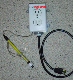
1 Standard AC outlet
1 Powercord with 3 pronged plug
1 Housing; outdoor outlet boxes work well and are water resistant
Soldering iron, solder, heavy duty electrical wire, light duty electrical wire, wire strippers, multimeter, screwdrivers, long nose pliers, etc.
Schematic Overview:
Although it is up to you to isolate current flowing through the float switches as best you can it is recommended to keep the voltage as low as possible in case of stray voltage. As with any float switch it is recommended a grounding probe be used. You may substitute a lower voltage transformer if you wish, but realize the coil voltage of the relays must match the transformer voltage.
Lets start with the left circuit. For this circuit you may use light gauge electrical wire rated for 12VDC. Wire one side of the transformer to one lead from the float switch. Solder the other side of the transformer to one side of the coil. Solder the other lead of the float switch to the opposite side of the coil.
|
|
This is a diagram from the RadioShack 275-206c 12VDC relay. It is a DPDT relay, but a SPDT will work. Note the coil is pins 13 & 14. Think of the coil voltage as the signal required to make the relay switch from normally closed to normally open. Pin 9 is the switch. Pins 1 and 5 are the contacts, normally closed and normally open respectively. When the signal voltage is not applied to the coil pins 1 & 9 are closed. When the signal voltage is applied to the coil pins 5 & 9 are closed. Note: the voltage of the coil only pertains to the signal required to make the contacts switch. The contacts have their own rating. In the top circuit a 12VDC coil switches 120VAC at the contacts. |
Now lets start the right circuit. Use heavy gauge electrical wire rated for 120VAC. Solder the black, or live, wire to the normally open pin of the relay. Solder a wire to the switch pin and connect it to the polarized side of the outlet. Connect the other side of the outlet to the white wire. If you purchased a 3 pronged power cord connect the green ground wire as well.
Explanation Of Operation For Top-Off:
Mount the float switch at the desired water level in your sump or tank. When the water is at or above this level the float switch is open. This means that no current is sent to the coil of the relay. When water evaporates and the water level lowers the float switch will close. This means that current is sent to the coil of the relay causing the normally open contacts to close. This will energize the outlet turning on the pump. Once the pump has replenished the water and the water level rises above the float switch current will once again be cut to the coil and the outlet will de-energize.
Optional:
Sometimes it is handy to have a manual override. You can wire in a 3-way switch which would give you the following modes: (A) normal float switch operation, (B) on, (C) off. Substitute the 3-way switch for the float switch in the left circuit. Connect the float switch across the first pair of contacts (A). Connect a wire between the second pair of contacts (B). Connect nothing between the third pair of contacts (C).